 |
||||||||||||||||
|
||||||||||||||||
|
|
|
||||||||||||||
Wind Tunnel Balance 3.0 Tilter adjusting procedure This procedure is for adjusting the Tilter on a WTB 3.0 axis with a Sensotec 250 gram load cell. These images use a Sensotec GM indicator, but the same procedure applies for similar signal conditioning equipment. The GM indicator shown here has been adjusted to display force in Newtons; however, it can be calibrated for other units of force and an appropriate decal inserted. |
||||||||||||||||
 |
||||||||||||||||
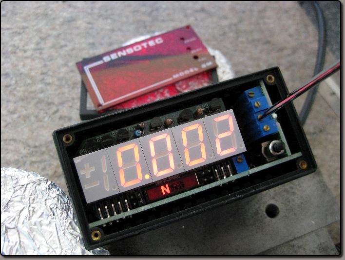
In this image the red cover of the GM indicator has been removed for access to the coarse span and course zero adjustments. With the red cover in place, the coarse adjustments are not accessable. This indicator has already been adjused for Newtons. |
||||||||||||||||
 |
||
This image shows the fine zero of the GM indicator being set. Note that the Magnet Rod is removed so the load cell has no load on it. It is from this no load position that the maximum limits must be observed. In this case +250 and -250 grams. |
||
 |
||
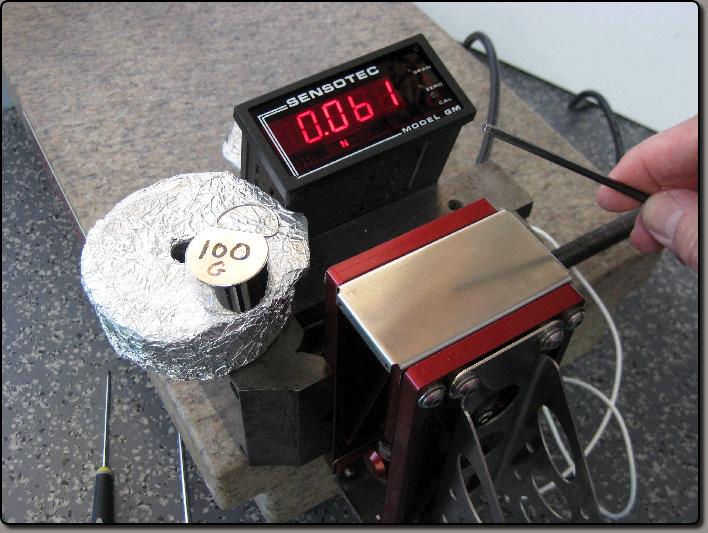
First loosen the Tilter just so it slides freely, then carefully insert the Magnet Rod. The mass of the Magnet Rod and loosened Tilter is showing on the indicator. In a horizontal position there should be little change on the indicator when the magnet rod is inserted. If the test model were mounted to the support, its mass would register as well. It is important to note that the flexures can be used to support most if not all of the mass of the model support and model. The flexures can be bent to accomplish this. |
||
 |
||
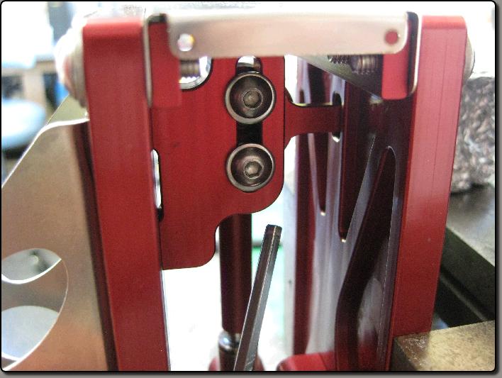
This image shows the Tilter adjusting screws. Carefully adjust, very lightly at first, the two screws on the Tilter. Note the indicator after making an adjustment and try to zero the indicator using the Tilter. It is very difficult to get it to zero, just get it close. Pay particular attention to the parallelism of the two plates of the Tilter. If the Tilter becomes saturated, (more than 5 degrees out of plane), loosen the two Tilter screws again and adjust the screws so the just become tight when the Tilter plates are again parallel wit the Magnet Rod in place. |
||
 |
||
In this image the Tilter has been adjused close enough. This has let the mass of the model, the model support, the active side of the axis, and the Magnet Rod all be supported by the spring of the flexures. As mentioned, the flexures can be bent slightly to help support the mass of the model with the axis limit stop approximately centered before any load is placed on the load cell. Gently rotate the Magnet Rod to verify that it is still properly seated on the sphere on the Tilter and hemisphere on the load cell. |
||
 |
||
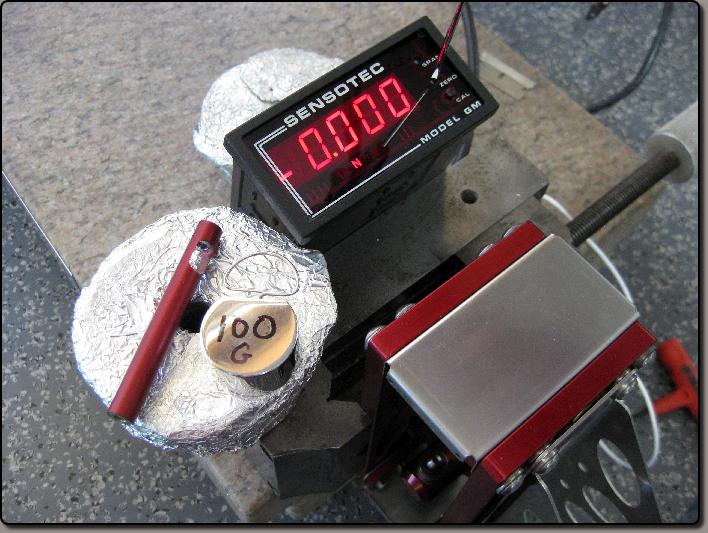
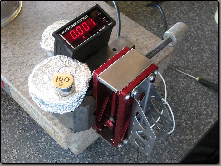
In this image the final zero has been accomplished with the zero on the sensotec GM indicator. After adjusing the GM to zero and before the image was take, the reading drifted to .001 newtons. This is normal and drifting errors even greater than that can be expected. Temperature, poor shielding, vibration, are some of the sources of drift. |
||
 |
||
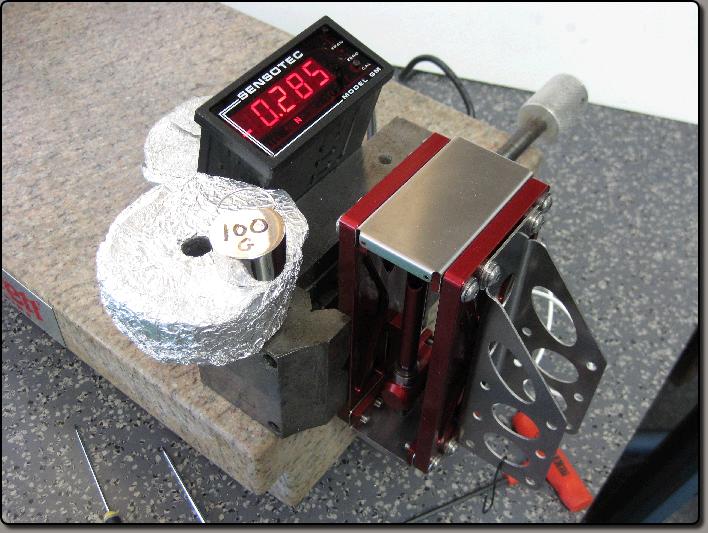
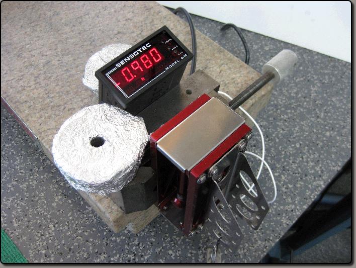
In this image the 100 gram mass has been added to the hook hanging on the model support bracket and we are reading .98 N. Some adjustment of the Span, fine and possibly coarse, on the GM will be needed to achieve correct calibration with no load and the calibration load. The reading was drifting between .978 and .983 which is normal when measuring these small forces. |
||